This is a duplicate of the Arch & Design Overview document by Autodesk and not written by Mr. Bluesummers.
This topic serves as an introduction to the Arch & Design material for mental ray.
What Is the Arch & Design Material?
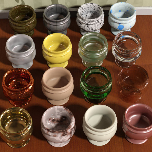
The mental ray Arch & Design material is a monolithic material shader designed to support most materials used in architectural and product-design renderings. It supports most hard-surface materials such as metal, wood and glass. It is especially tuned for fast glossy reflections and refractions (replacing the DGS material) and high-quality glass (replacing the dielectric material).
The major features are:
- Easy to use, yet flexible – controls are arranged logically in a most-used-first fashion.
- Templates – allow fast access to settings combinations for common materials.
- Physically accurate – the material is energy conserving, making it impossible to create shaders that break the laws of physics.
- Glossy performance – advanced performance boosts including interpolation, emulated glossiness, and importance sampling.
- Tweakable BRDF (bidirectional reflectance distribution function) – the user can define how reflectivity depends on angle.
- Transparency – “Solid” or “thin” materials: transparent objects such as glass can be treated as either solid (refracting, built out of multiple faces) or thin (nonrefracting, can use single faces).
- Round corners – simulate fillets to allow sharp edges to still catch the light in a realistic fashion.
- Indirect Illumination control – set the final gather accuracy or indirect illumination level on a per-material basis.
- Oren-Nayar diffuse – allows “powdery” surfaces such as clay.
- Built-in Ambient Occlusion – for contact shadows and enhancing small details.
- All-in-one shader – photon and shadow shader built in.
- Waxed floors, frosted glass and brushed metals – all fast and easy to set up.
Physics and the Display
The Arch & Design material attempts to be physically accurate, hence its output has a high dynamic range. How visually pleasing the material looks depends on how colors inside the renderer are mapped to colors displayed on the screen.
When rendering with the Arch & Design material it is highly recommended that you operate through a tone mapper/exposure control such as the mr Photographic Exposure Control in conjunction with gamma correction, or at the very least use gamma correction.
A Note on Gamma
Describing all the details of gamma correction is beyond the scope of this topic; this is just a brief overview.
The color space of a normal, off-the-shelf computer screen is not linear. The color with RGB value 200 200 200 is not twice as bright as a color with RGB value 100 100 100, as one might expect.
This is not a bug because, due to the fact that our eyes see light in a nonlinear way, the former color is actually perceived to be about twice as bright as the latter. This makes the color space of a normal computer screen roughly perceptually uniform. This is a good thing, and is actually the main reason 24-bit color (with only 8 bits or 256 discrete levels for each of the red, green and blue components) looks as good as it does to our eyes.
The problem is that physically correct computer graphics operates in a true linear color space where a value represents actual light energy. If one simply maps the range of colors output to the renderer naively to the 0–255 range of each RGB color component it is incorrect.
The solution is to introduce a mapping of some sort. One of these methods is called gamma correction.
Most computer screens have a gamma of about 2.2 (known as the sRGB color space), but 3ds Max defaults to a gamma of 1.8, which makes everything look too dark (especially midtones), and light does not “add up” correctly.
Using a gamma of 2.2 is the theoretically correct value, making the physically linear light inside the renderer appear in a correct linear manner on screen.
However, because the response of photographic film isn’t linear either, users find that this theoretically correct value looks too bright and washed out. A common compromise is to render to the default gamma of 1.8, making things look more photographic; that is, as if the image had been shot on photographic film and then developed. However, when exporting and importing images (for example, as texture maps) with external image-editing programs, for best results set all gamma values on Preferences > Gamma and LUT Preferences to 2.2.
Tone Mapping
Another method for mapping the physical energies inside the renderer to visually pleasing pixel values is known as tone mapping. You can accomplish this either by rendering to a floating-point file format and using external software, or with a plug-in that allows the renderer to do it on the fly. In 3ds Max such plug-ins are known as exposure controls and are accessed from the Environment dialog.
Use Final Gathering and Global Illumination
The Arch & Design material is designed to be used in a realistic lighting environment; one that incorporates full direct and indirect illumination.
mental ray provides two basic methods for generating indirect light: Final Gathering and Global Illumination. For best results, be sure to use at least one of these methods.
At the very least, enable Final Gathering, or use Final Gathering combined with Global Illumination (photons) for quality results. Performance tips for using Final Gather and Global Illumination can be found here.
If you use an environment for your reflections, make sure the same environment (or a blurred copy of it) is used to light the scene through Final Gathering. In 3ds Max this means you should include a Skylight in your scene set to Use Scene Environment, or use Daylight system with Skylight set to mr Sky.
Use Physically Correct Lights
Traditional computer-graphics light sources live in a cartoon universe where the intensity of the light doesn’t change with the distance. The real world doesn’t agree with that simplification. Light decays when leaving a light source due to the fact that light rays diverge from their source and the intensity of the light changes over distance. This decay of a point light source is 1/d2; in other words, light intensity is proportional to the inverse of the square of the distance to the source.
One of the reasons for this traditional oversimplification is the fact that in the early days of computer graphics, tone mapping was not used and problems of colors blowing out to white in the most undesirable ways was rampant. (Raw clipping in sRGB color space is displeasing to the eye, especially if one color channel clips earlier than the others. Tone mapping generally solves this by “soft clipping” in a more suitable color space than sRGB.)
However, as long as only Final Gathering (FG) is used as indirect illumination method, such traditional simplifications still work. Even light sources with no decay still create reasonable renderings. This is because FG is concerned only with the transport of light from one surface to the next, not with the transport of light from the light source to the surface.
It’s when working with Global Illumination (GI) (that is, with photons) the troubles arise.
When GI is enabled, light sources shoot photons. For the Arch & Design material (or any other mental ray material) to be able to work properly, it is imperative that the energy of these photons to match the direct light cast by that same light. And since photons model light in a physical manner, decay is built in.
Hence, when using GI:
Light sources must emit photons at the correct energy.
The direct light must decay in a physically correct way to match the decay of the photons.
Therefore it is important to make sure the light shader and the photon emission shader of the lights work well together.
In 3ds Max this is most easily solved by using the photometric lights. All of these lights are guaranteed to have their photon energy in sync with their direct light. It is built in and automatic and one does not need to worry about it.
Features
The Shading Model
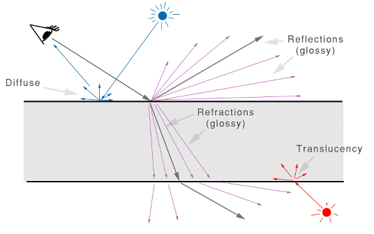
From a usage perspective, the shading model consists of three components:
- Diffuse – diffuse channel /including Oren Nayar “roughness”).
- Reflections – glossy anisotropic reflections (and highlights).
- Refraction – glossy anisotropic transparency (and translucency).
Direct and indirect light from the scene cause diffuse reflections as well as translucency effects. Direct light sources also create specular highlights.
Ray tracing is used to create reflective and refractive effects, and advanced importance-driven multi-sampling is used to create glossy reflections and refraction.
The rendering speed of the glossy reflections/refraction can further be enhanced by interpolation as well as “emulated” reflections with the help of Final Gathering.
Conservation of Energy
One of the most important features of the material is that it is automatically energy conserving. This means that it makes sure that diffuse + reflection + refraction <= 1. In other words, no energy is magically created and the incoming light energy is properly distributed to the diffuse, reflection and refraction components in a way that maintains the first law of thermodynamics.
In practice, this means, for example, that when adding reflectivity, the energy must be taken from somewhere, and hence the diffuse level and the transparency will be automatically reduced accordingly. Similarly, adding transparency happens at the cost of the diffuse level.
The rules are as follows:
- Transparency takes energy from diffuse; that is, at 100% transparency, there is no diffuse at all.
- Reflectivity takes energy from both diffuse and transparency; that is, at 100% reflectivity there is neither diffuse nor transparency.
- Translucency is a type of transparency, and the Translucency Weight parameter defines the percentage of transparency vs. translucency.
Conservation of energy also means that the level of highlights is linked to the glossiness of a surface. A high Reflection Glossiness value causes a narrow, intense highlight, while a lower value causes a wider, less intense highlight. This is because the energy is now spread out and dissipated over a larger area.
BRDF: How Reflectivity Depends on Angle
In the real world, the reflectivity of a surface is often view-angle dependent. A fancy term for this is bidirectional reflectance distribution function (BRDF); that is, a way to define how much a material reflects when seen from various angles.
Many materials exhibit this behavior. The most obvious examples are glass, water, and other dielectric materials with Fresnel effects (where the angular dependency is guided strictly by the index of refraction), but other layered materials such as lacquered wood and plastic display similar characteristics.
The Arch & Design material allows this effect to be defined by the index of refraction, and also allows an explicit setting for the two reflectivity values for:
- 0 degree faces (surfaces directly facing the camera)
- 90 degree faces (surfaces 90 degrees to the camera)
Reflectivity Features
The final surface reflectivity is in reality caused by the sum of three components:
- The diffuse effect
- The actual reflections
- Specular highlights that simulate the reflection of light sources
In the real world, highlights are just glossy reflections of the light sources. In computer graphics it’s more efficient to treat these separately. However, to maintain physical accuracy the material automatically keeps highlight intensity, glossiness, anisotropy, etc. in sync with the intensity, glossiness and anisotropy of reflections. Thus, there are no separate controls for these as both are driven by the reflectivity settings.
Transparency Features
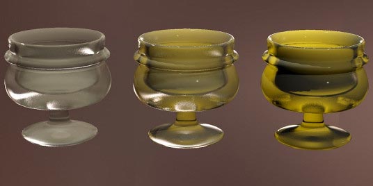
The material supports full glossy anisotropic transparency and includes a translucent component, described in detail here.
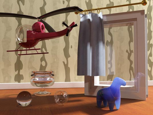
Solid versus Thin-Walled
The transparency/translucency property can treat objects as either solid or thin-walled.
If all objects were treated as solids at all times, every window pane in an architectural model would have to be modeled as two faces: an entry surface that refracts the light slightly in one direction, and immediately following it an exit surface, where light is refracted back into the original direction.
Not only does this entail additional modeling work, it is a waste of rendering power to simulate refraction that has very little net effect on the image. Hence the material allows modeling the entire window pane as a single flat plane, foregoing any actual refraction of light.
In the preceding illustration the helicopter canopy, the window pane, the translucent curtain, and the right-hand sphere all use thin-walled transparency or translucency, whereas the glass goblet, the plastic horse, and the left-hand sphere all use solid transparency or translucency.
Cutout Opacity
Beyond the “physical” transparency, which models an actual property of the material, the material provides a completely separate, non-physical “cutout opacity” channel to allow “billboard” objects such as trees, or to cut out objects such as a chainlink fence with an opacity mask.
Special Effects
Built-in Ambient Occlusion
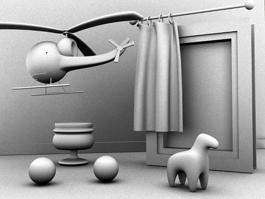
Ambient Occlusion (AO) is a method spearheaded by the film industry for emulating the look of true global illumination by using shaders that calculate the extent to which an area is occluded, or prevented from receiving incoming light.
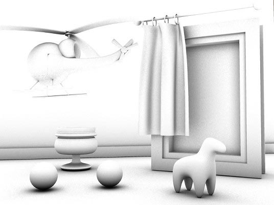
Used alone, an AO shader, such as the separate mental ray Ambient/Reflective Occlusion shader, creates a grayscale output that is dark in areas light cannot reach and bright in areas where it can:
The following image illustrates the main results of AO: dark crevices and areas where light is blocked by other surfaces, and bright areas that are exposed to the environment.
One important aspect of AO is that the user can how far it looks for occluding geometry.
Using a radius creates a localized AO effect: Only surfaces within the given radius are considered as occluders. This also speeds up rendering. The practical result is that the AO provides nice “contact shadow” effects and makes small crevices visible.
The Arch & Design material gives you two ways to utilize its built-in AO:
- Traditional AO for adding an omnipresent ambient light that is then attenuated by the AO to create details.
- Use AO for detail enhancement together with existing indirect lighting methods such as Final Gathering or photons.
The latter method is especially interesting when using a highly smoothed indirect illumination solution, such as a high photon radius or an extremely low final gather density, which could otherwise lose small details. By applying the AO with short rays these details can be brought back.
Round Corners
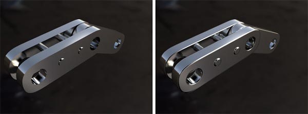
Computer-generated imagery tends to look unrealistic, partly because edges of objects are geometrically sharp, whereas most edges in the real world are slightly rounded, chamfered, worn, or filleted in some manner. This rounded edge tends to “catch the light” and create highlights that make edges more visually appealing.
The Arch & Design material can create the illusion of rounded edges at render time. This feature is intended primarily to speed up modeling, so that you need not explicitly fillet or chamfer edges of objects such as a tabletop.
The function is not a displacement; it is merely a shading effect, like bump mapping, and is best suited for straight edges and simple geometry, not advanced, highly curved geometry.
Performance Features
Finally, the Arch & Design material contains a large set of built-in functions for optimal performance, including but not limited to:
- Advanced importance sampling with ray rejection thresholds
- Adaptive glossy sample count
- Interpolated glossy reflection/refraction with detail enhancements
- Ultra-fast emulated glossy reflections (Highlights+FG Only mode)
- The option to ignore internal reflections for glass objects
- The choice between traditional transparent shadows, suitable for objects such as a window pane, and refractive caustics, suitable for solid glass objects, on a per-material basis.


By fabio December 16, 2010 - 6:30 pm
excuse me so much.
i got a problem. my arch and design library doesnt work anymore
u know a possible explanation for this?